Categories: all aviation Building a Biplane bicycle gadgets misc motorcycle theater
Thu, 12 Jan 2012
The Penultimate in ADI Progress
After a fairly annoying day, I came home with a freshly-printed transparency of the top paste layer for the ADI board -- that is, what would soon become my solder stencil. I'm using solder paste on this project, and this allows me to apply it in a single swipe.
The advice from Sparkfun on creating a solder paste stencil is that you send out your stencil files, and have a production house do it. They also say, several different ways, that this is nowhere near the critical step you might think it is -- in other words, that close is good enough.
I took that advice to heart, and decided that I would give it a try in the most homebrewed way possible. I opened up the circuit board in Eagle, and selected only the tPaste layer to view. I printed this out, onto a standard laser jet transparency that I picked up at an office supply store. The box claims that it's a 5.3 mil thick sheet.
When I got home, transparency and new X-acto knife in hand, I very carefully cut just inside the tPaste lines (and only cutting out a smaller square in the middle of the CR2032's minus pad). This resulted in a somewhat amateurish, but serviceable-looking stencil. Granted, I wouldn't want to do this for hundreds of SMT devices, but for my three devices, it wasn't bad.
After that, I just swiped away with the paste (also from Sparkfun) and a utility razor blade. Voila! I did it twice, rejecting the first one as being a bit too messy on the BMP085, which has miniscule pads. The second attempt wasn't any better, so I just very carefully separated the adjoining solder paste blobs with the razor knife, and called it good enough.
I borrowed a hotplate from a friend who's treaded this path before me, in order to do the heating. The idea (as documented by Sparkfun here) is that you apply the paste, drop your components in place, then stick the whole mess on a hotplate or skillet. You heat it up until the solder liquifies, then you pull it off and let it cool down.
That is, more or less, what I did. I had checked beforehand with my handy IR thermometer, and found that this particular hotplate had a hotter spot in one area, so I determined that I would stick my board there. I cranked that sucker up to HIGH, dropped the board on the hotspot, and watched it carefully. Within about a minute, all the solder had gone liquid, and I pulled it off.
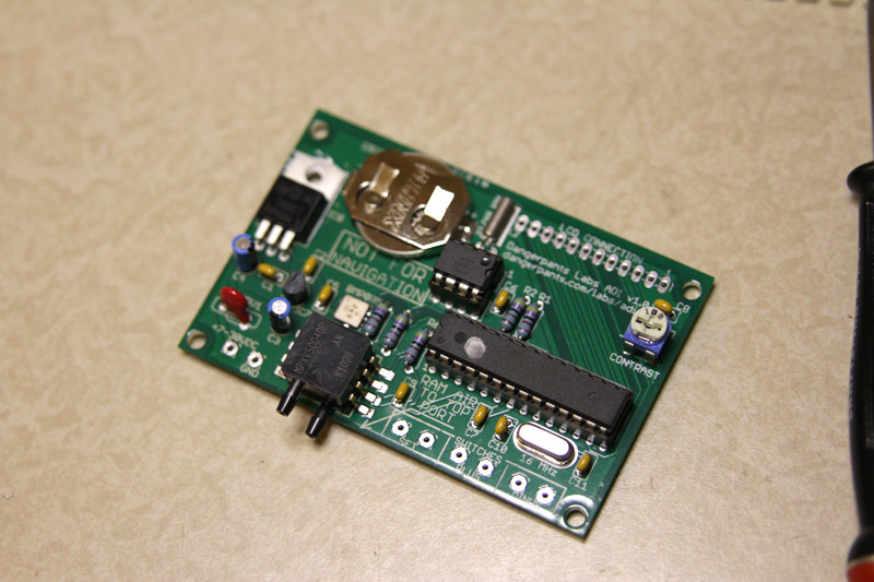
I actually think the heat was up too high (the plate itself got up over 320°C), as the board got a little scorched-looking on the bottom. I think it could have been set to a lower temperature and still done the job just fine. But scorching aside, the board looked great, and testing revealed no solder bridges on the BMP085, which was my only real concern.
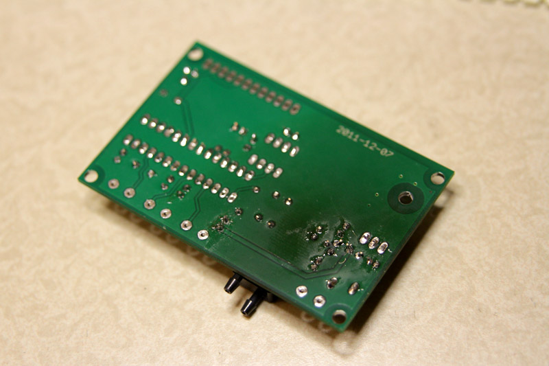
The downside to this approach is that I now had a handful of components stuck to the board, and any real chance of doing a phased installation, with intermittent smoke checks, was gone. So I stuffed the whole board and soldered it all up. It looks great, but I haven't taken the final step of applying 7-30 VDC to the input terminal to see what goes foom.
In documenting the LCD connector, I did discover that I made one mistake: the pin 12 connection should be to ground, not to +5v. It's easy to work around, just don't attach a wire from pin 12 to the LCD, but it's a little silly. That fix will go into the next version.
My next step is to take my fate firmly by the horns, apply power, and see where the smoke escapes. For now, I think I'm going to go to bed while I can still ride the good feeling of making progress, without the disappointment of destroying components. Leave that for another day.
Posted at 23:59 permanent link category: /gadgets
Categories: all aviation Building a Biplane bicycle gadgets misc motorcycle theater