Categories: all aviation Building a Biplane bicycle gadgets misc motorcycle theater
Mon, 01 May 2017
Building a Biplane: The First (Almost) Real Part
I have just finished the first physical part that is very nearly a real airplane part, in my nascent project to build a Marquart Charger biplane.
As I mentioned last time, I'm going to start on the ribs. In the intervening time, I've gotten the floor painted, built my (first) worktable, and started moving stuff in to the garage. I also acquired my welding equipment, but that's a topic for a different post.
The worktable, conveniently, is built with a 3/4" MDF top surface. It's 33" by 8', so there was a convenient strip of MDF left over from that project. I've now measured and marked the airfoil coordinates onto a piece of that MDF for the rib jig, but lacking 1/4" wood, had to set it aside for a moment. I am not going to print out the rib from the plans at full scale, since I've already found a couple of minor drafting errors, and will work off the printed measurements instead. To some extent, the exact dimensions of the internal structure of the rib isn't very important, and long as it's consistent between ribs. I will naturally be striving to be as close to plans as possible, but there's likely to come a time when I'll have to choose between how it's drawn, and how it's measured.
In any case, lacking the capstrip, but having the MDF, I decided to proceed with the rib nose template. This ended up being (like probably every single thing I do on this project) easier said than done.
First, I grabbed a sheet of graph paper, and measured out the coordinates of the airfoil, as far as the nose would go, and drew it out with the help of a somewhat precariously grasped steel ruler to approximate the curves between points. I also discovered that my graph paper grid was neither quite exactly straight nor quite exactly 1/4" per square. So, marginal. Still, it looked nice on paper.
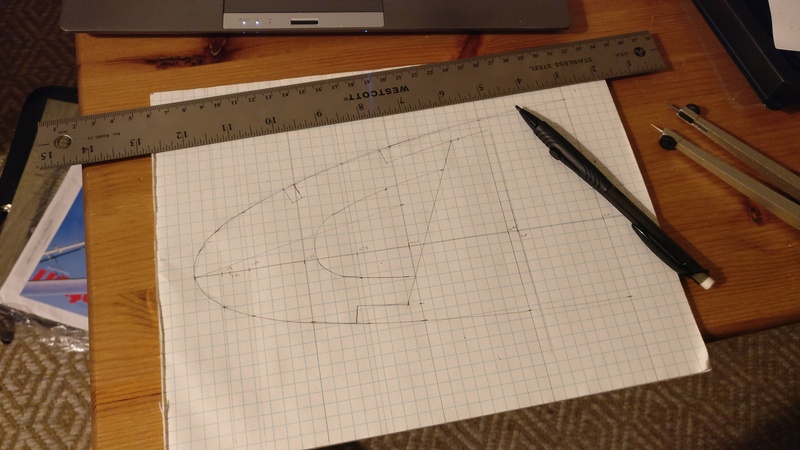
One problem quickly presented itself, though: what was up with these notches? The nosepiece is notched with 1/4" by 3/8" cutouts, for stringers that run along the leading edge, supporting the sheet of thin aluminum that makes up the leading edge of the wing. But the stringers called out in the later plans were 3/8" by 3/8", not 1/4" by 3/8". Hmm. I asked the question on the Biplane Forum, and the general consensus was that since I was planning on plywood leading edges anyway (generally stiffer and more resilient than aluminum, though probably a touch heavier than the very thin Al called for in the plans), I could just omit the stringers. The plywood would be plenty strong enough to support itself without stringers. Also, bonus: one less order of expensive spruce to buy.
So, that bit of mental gymnastics out of the way, I decided to draw out the nosepiece in CAD, so I could be 100% sure I had the airfoil shape right. One of the comments in the thread pointed me to airfoiltools.com, which gave me a plot of 80 points of the NACA 2412 airfoil that the Charger uses. I saved that list of points to a file (here if you want it), and wrote a quick Python script, which turned into a quick FreeCAD macro (here, but you'll need to modify the file location to suit your installation) that draws out the airfoil for you. If there's enough interest, I may update that macro to handle other airfoils, but at the moment it just does the one.
Anyway, I now had a way to quickly and easily draw a correct NACA 2412 airfoil in FreeCAD, but making the nosepiece shape was more complicated. I ended up spending about 5 hours farting around trying to make FreeCAD do what I wanted, before I figured it out (email me if you want details, it's too far into the weeds for this post). Of course, now that I've figured out how to do it, I can make the nosepiece in about 10 minutes.
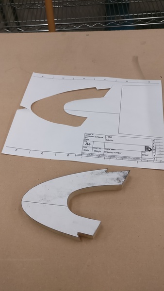
All that work resulted in this PDF file of the drawing, which, if you print it out at 100% scale (it slightly overprints on Letter size paper, but the nosepiece is all there), gives you a 100% size, accurate drawing of the nosepiece.
Finally, finally, I was ready to make the MDF template. I carefully cut out the template from the printed sheet, and glued it down to the MDF. The jigsaw took away most of the excess, except on the inside edge, where I couldn't quite turn quickly enough, and had to leave a big chunk. I busted out the files, and started the long, tedious work of filing down the last little bit of MDF to exactly match the printout.
Two hours later, I was the comparatively proud owner of one rib nose template, lovingly handcrafted out of artisanal fiberboard.
This will be the master template, from which I'll use the router to make a copy in MDF, which will then be used to cut out actual rib nosepieces. The master will get locked away somewhere safe, so that if I mess up the copy template, I can make another one that will hopefully be exactly the same. It's a good theory, anyway.
It's nice, finally, to be making airplane parts (or very nearly airplane parts). The build feels like it's almost started. Only 11 years after I first started thinking seriously about it. As occurs to me every time I ponder it, if I had only started then, I'd be done by now!
Posted at 22:32 permanent link category: /charger
Categories: all aviation Building a Biplane bicycle gadgets misc motorcycle theater