Categories: all aviation Building a Biplane bicycle gadgets misc motorcycle theater
Tue, 19 Jan 2021
Building a Biplane: Build Order
When I started on this whole biplane wheeze, one of the first questions (after "Which one to build") was what order to build things in. There are basically two answers to this question, broadly speaking: you can build the fuselage first, or you can build the wings first. The fuselage is a welded steel structure that will be about 18 feet long, two feet wide, and three feet tall when it's assembled. The wings are four 12 foot long, 5 foot wide, 9 inch thick wooden structures composed of thousands of little sticks glued together, more or less.
I decided to build wings first, because I was more comfortable working in wood, basically. At the time, I didn't know how to weld, and had few metalworking tools that would be useful for building the fuselage. The wings were the obvious choice.

The first rib I built, waiting for gussets
When building the wings, the first thing you build is wing ribs. This is a great place to start, because buying all the materials costs only a few hundred dollars (building a plane is a many tens-of-thousands of dollars investment, so this is indeed a very low-commitment way to start). Building the jig on which a rib is assembled is fairly straightforward, and the only complicated part to build at this point is the rib noses, which are funny-shaped pieces of plywood, which I ended up cutting on a router using a template double-stick taped to the roughed-out plywood shape.
To be sure, there are many factors that go into building ribs, it's not a simple process. But it's also not terribly hard, and because it's so low-commitment, you can get a good taste for Building Life, and see if it's really for you. In my case, it was, and I carried on.
I got a little ahead of myself as I drew to the close of the rib project, and ordered my spars. I'm not sad I did, as it took a long time for them to arrive (most of a year), but I had some other things I needed to tackle before the spars came into play.
In addition to ribs, the wings of a Marquart Charger are composed of a number of welded brackets, compression tubes, crisscrossing drag and anti-drag wires or strips, and a bunch of wedge blocks. Those brackets have to be painted or powder coated. You also need a bunch of AN hardware (fancy bolts) and turnbuckles (for drag strips) or clevis fork rod ends (for drag wires). Once you have all these things gathered together, you can start actually assembling a wing.
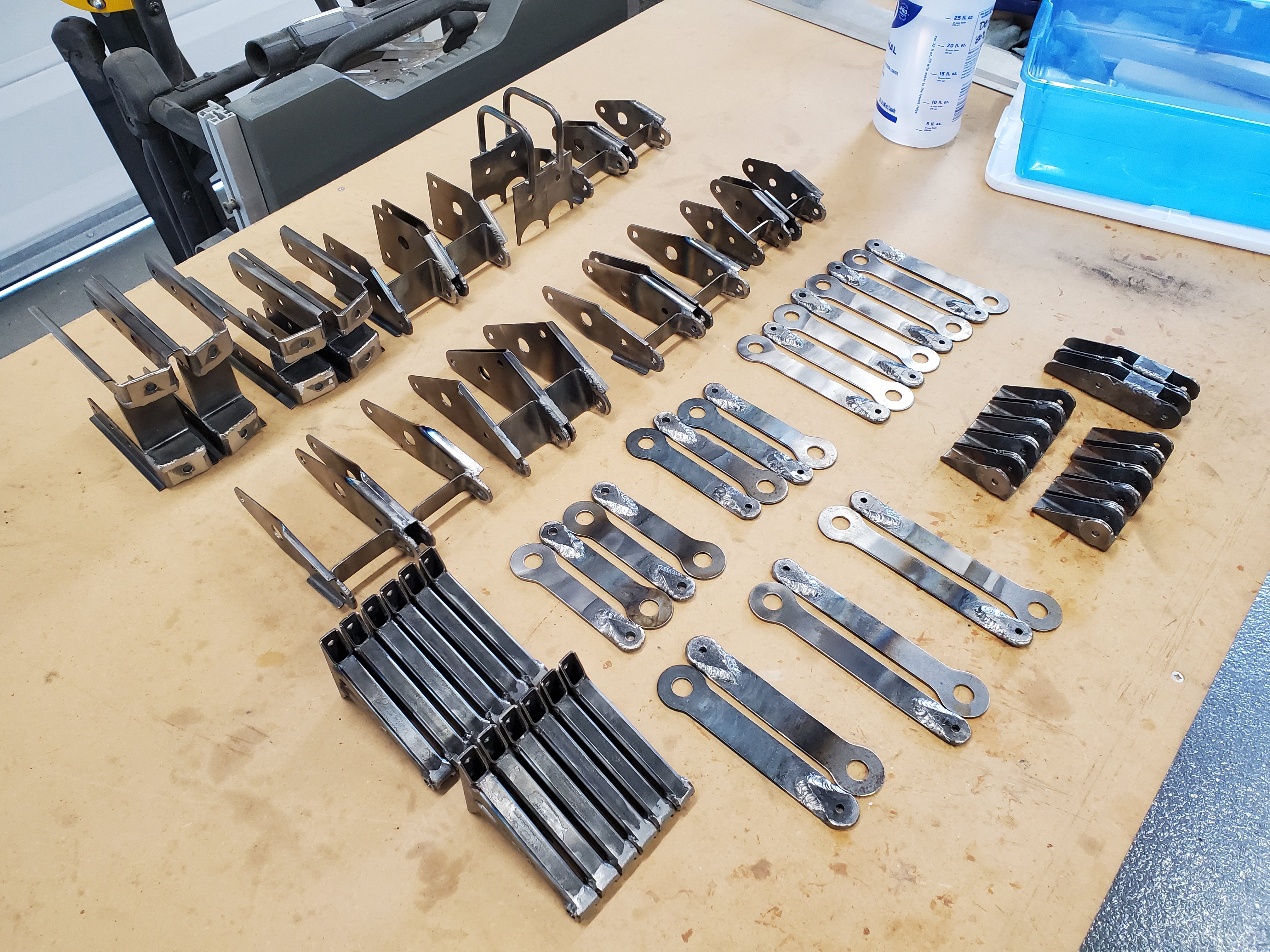
Many of the brackets that go into building a Charger wing (these
are brackets for all four wings, not just one)
This, broadly, is the process I'm in the middle of now. I've welded and painted all the brackets. I've made the compression tubes and have the drag wires started. I've cut all the wedges, in a cloud of shredded spruce. On the first day of December, 2020, I threaded the wing ribs onto the spars and began my wing build.
Thus I come to the point of this entry: listing out all the operations that go into assembling a wing, once you've made all the component parts.
Cutting the Spars
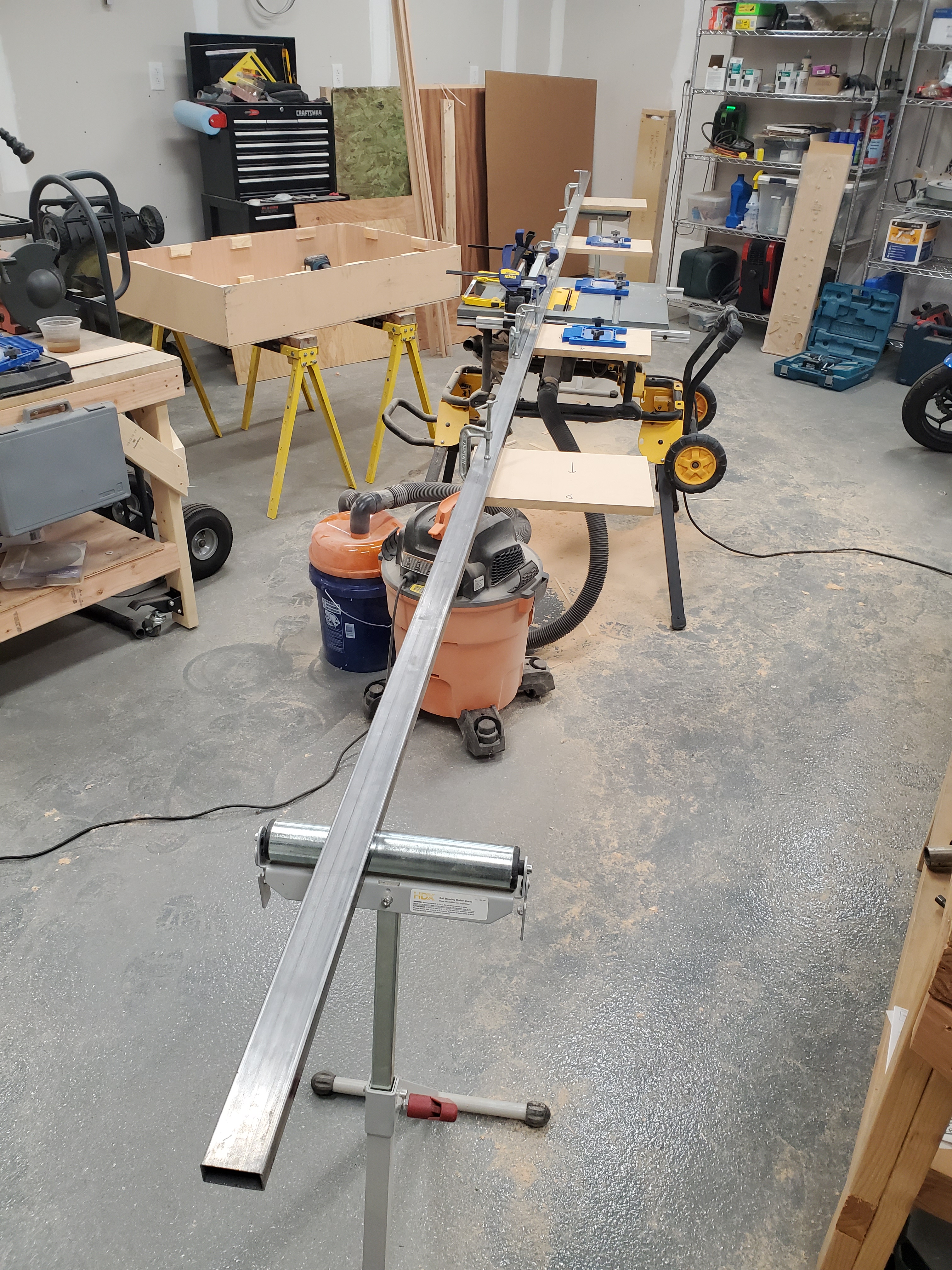
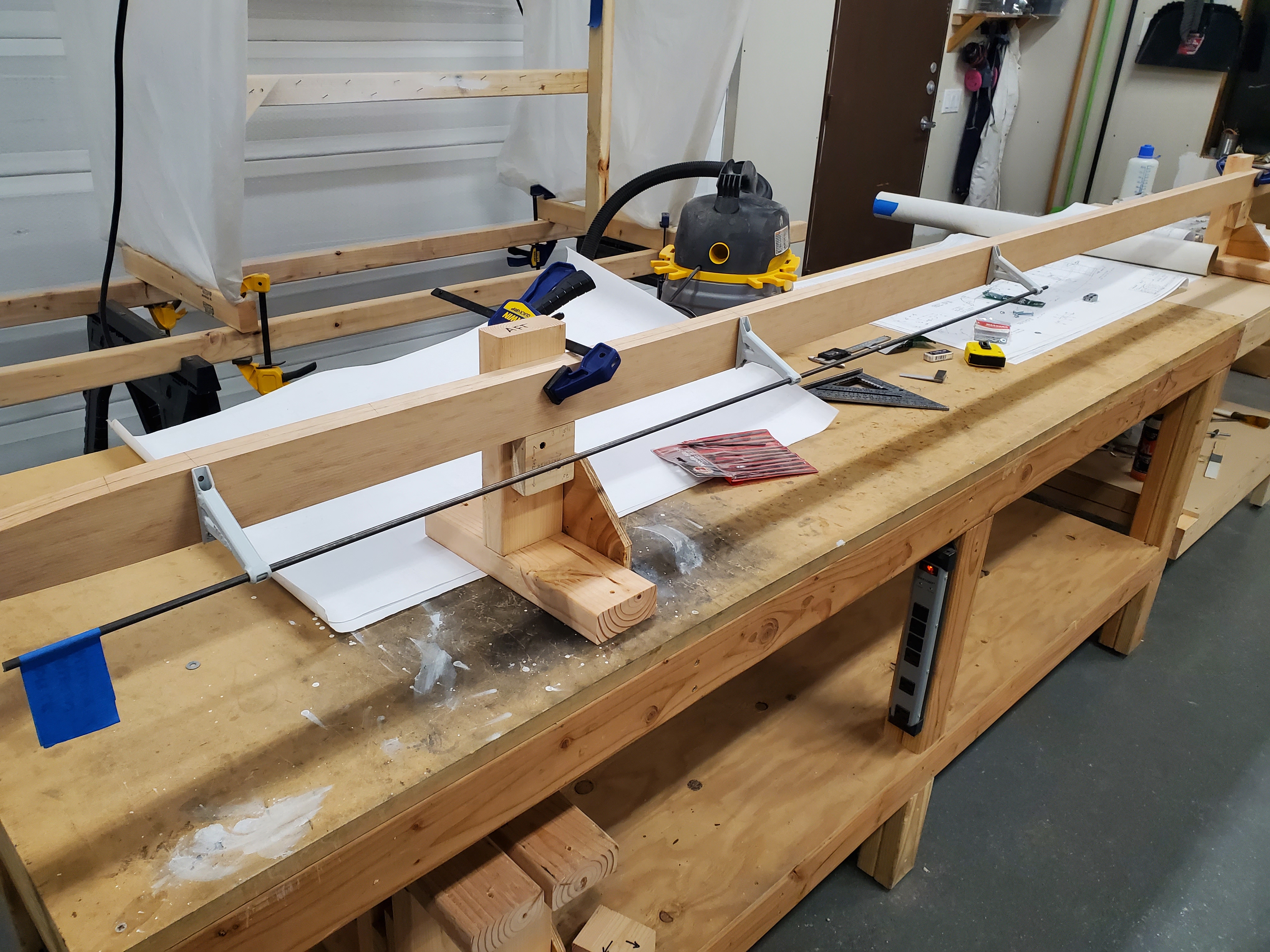
The Very Long Fence set up and ready to bevel some spars
First up, you have to take the spars, and cut the bevel angle in the top and bottom surfaces, so they'll match up to the ribs. To do this, I set up a Very Long Fence on my table saw, and used the saw to cut the angles. This was one of the scariest operations for me, just because it was something I'd never tried before, and aircraft grade spruce spar material is ridiculously hard to get hold of, so I was horrified I'd get it wrong. In the end, it wasn't bad, but I'm glad I did all the prep I did. Don't forget that you need left- and right-hand versions of the spars, and the bevels are different between the two.
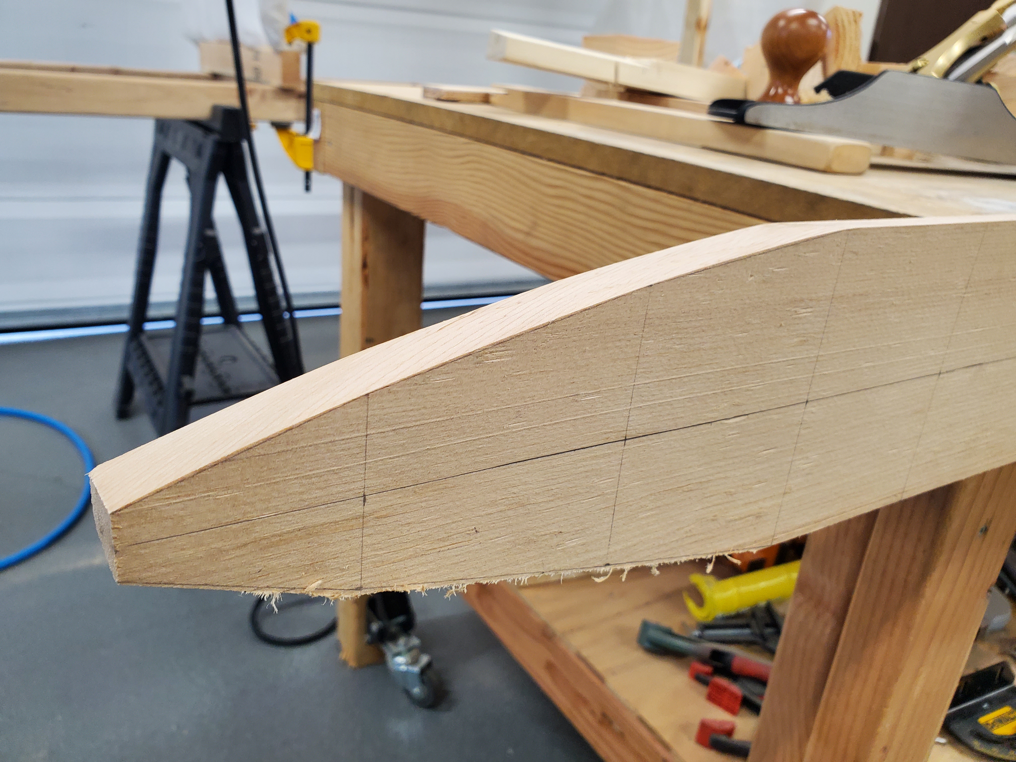
Tapering the end of the forward spar
Next up, the wingtip tapers down to a point, so you have to taper the ends of the spars. This was less scary, because I ordered my spars a bit too long, so I had some wiggle room if I screwed up the first time. Having drawn the tapers onto the spar face with a pencil, I ran a handheld circular saw just outside those lines, and used a hand plane to bring the surface down to the lines as exactly as I could. It was a slow process, but the results were good.
Marking the Spars
Put centerlines everywhere. I drew centerlines down the top face and the inboard face, and wished I'd drawn centerlines on the outboard faces as well. I haven't found a need for a centerline on the bottom face yet, but I can imagine it happening.
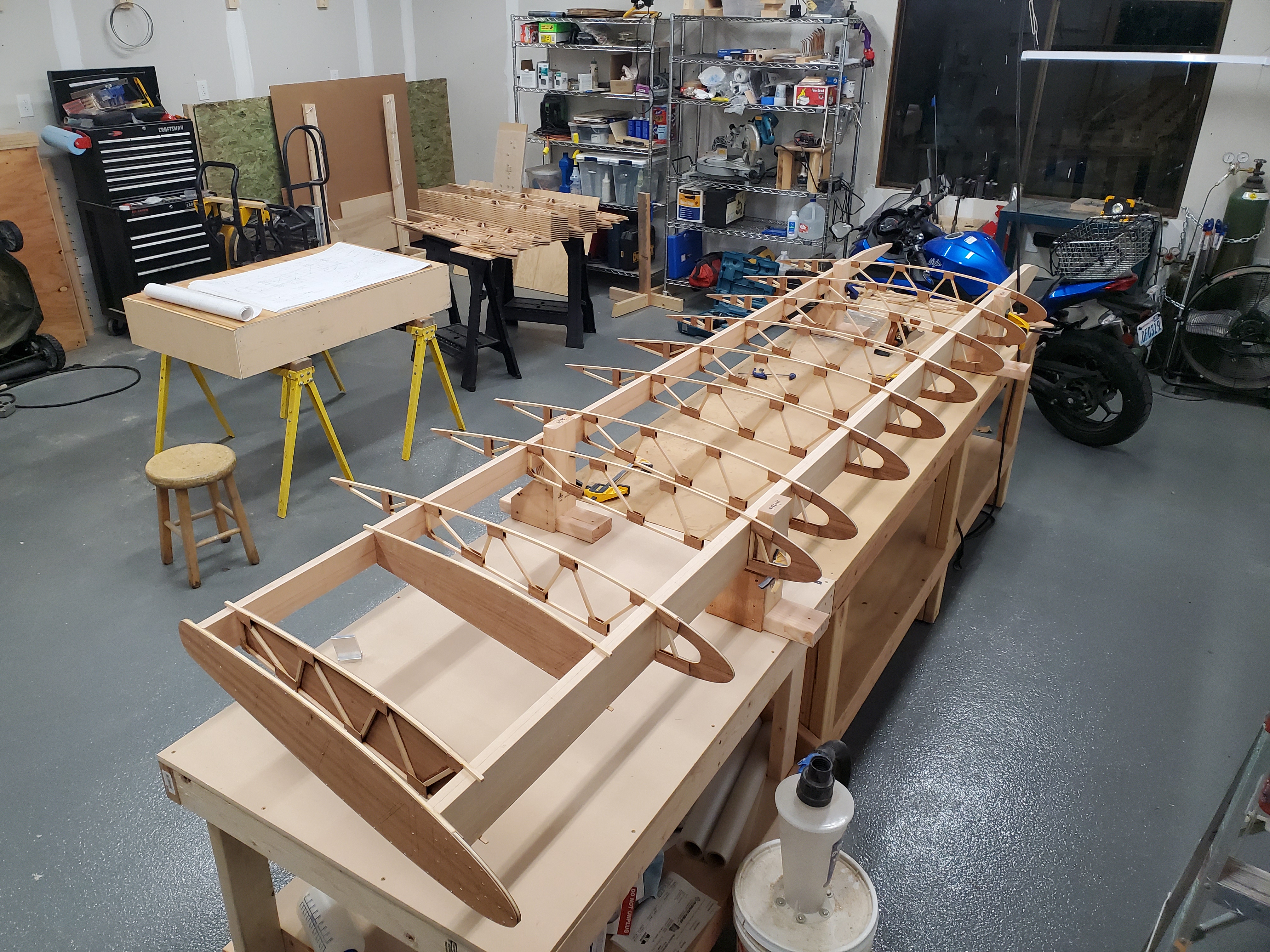
All the ribs lined up along the spars
Mark the locations of all the thingies that will go onto the spar: mostly ribs, but also the compression tubes, and the aileron pivots. These measurements are each marked from a reference point (I used the butt end of the spar), and are marked on the top centerline. Then, draw the line at the appropriate 10° angle to match the sweep of the wing. This becomes the reference line for the hole which will eventually be drilled through the wing, and will extend onto wedge blocks.
I wrote dash numbers near each line, so I could double-check that I had my spacing and part order correct, referring back to Sheet 2 of the plans a lot. Once the wedge blocks are glued on, those ribs are never coming off again, so you want to be sure they're in the right position and the right order.
Those Wedge Blocks
In addition to making these weird 10° and 20° cuts to form the wedge block, you have to cut them down to the matching size and angle once you have the spar bevelled. I trimmed them on the miter saw, which was alright, but setting the vertical angle on my miter saw isn't the easiest, and I had to do a lot of double-checking to make sure I was doing it right. I ended up setting my hand plane on its side, and running the edge of the wedge block against it to make small trims.
Once you're sure you've got the ribs on in the right order and they don't need any last minute surgery (I worried about whether I actually wanted to have a stringer on the noses, to keep them stronger during storage, but decided I'd make a removeable stringer that was notched to fit the ribs), it's time to glue the wedge blocks on.
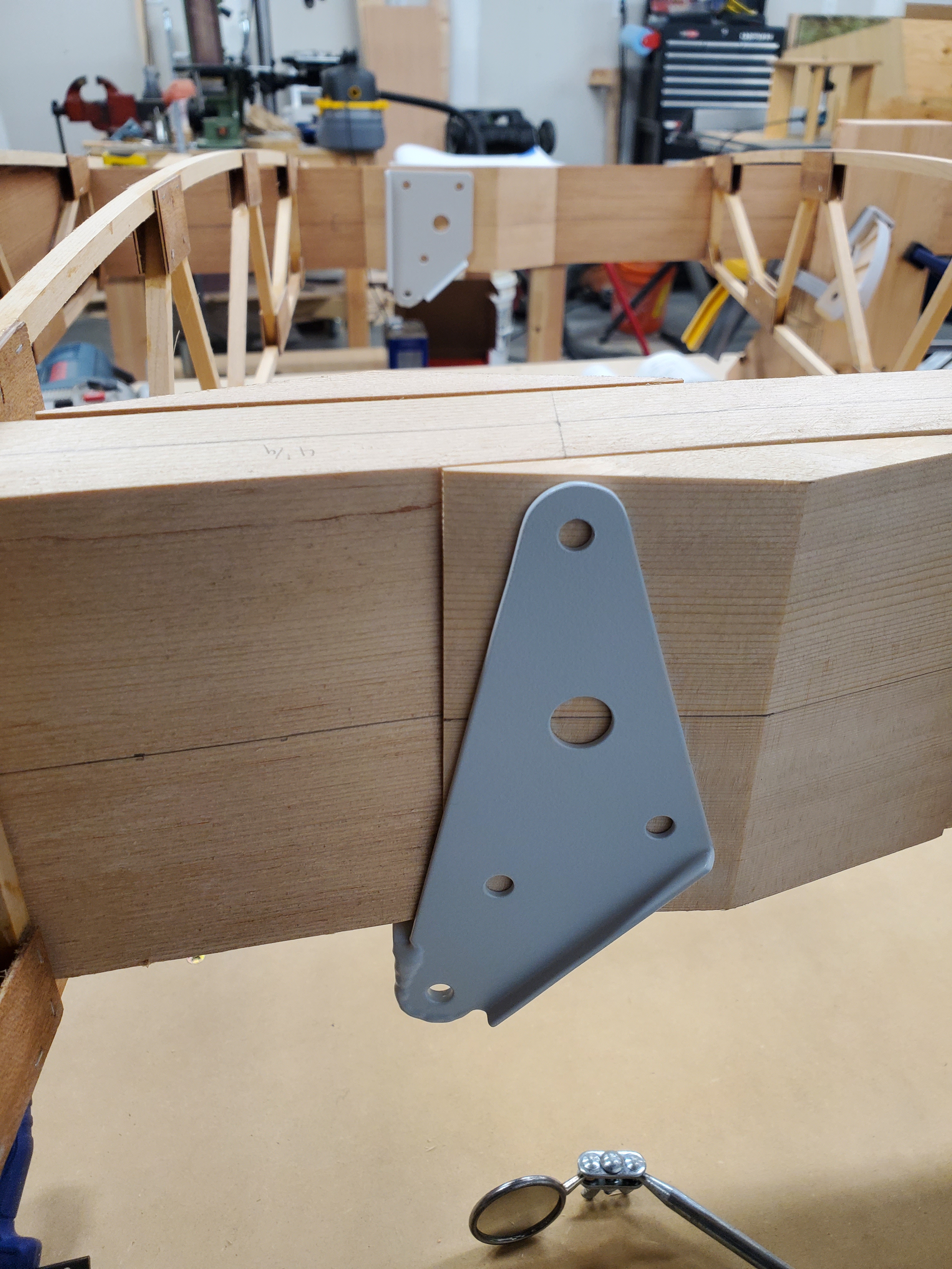
Test-fitting the forward cabane bracket
I tried fitting the brackets on with the wedges in place, and I'm glad I did: the forward cabane bracket really didn't want to slide inboard enough, without hitting the spar on the bottom forward corner. I ended up making it just barely fit by sanding the flat back of both wedges until the sharp edge had essentially no flat to it (the plans suggest 1/32" of flat). A better solution for this would be to make the brackets 1 9/16" wide instead of the specified 1 1/2", but that would have minor knock-on effects for the cabane structure and attachment hardware.
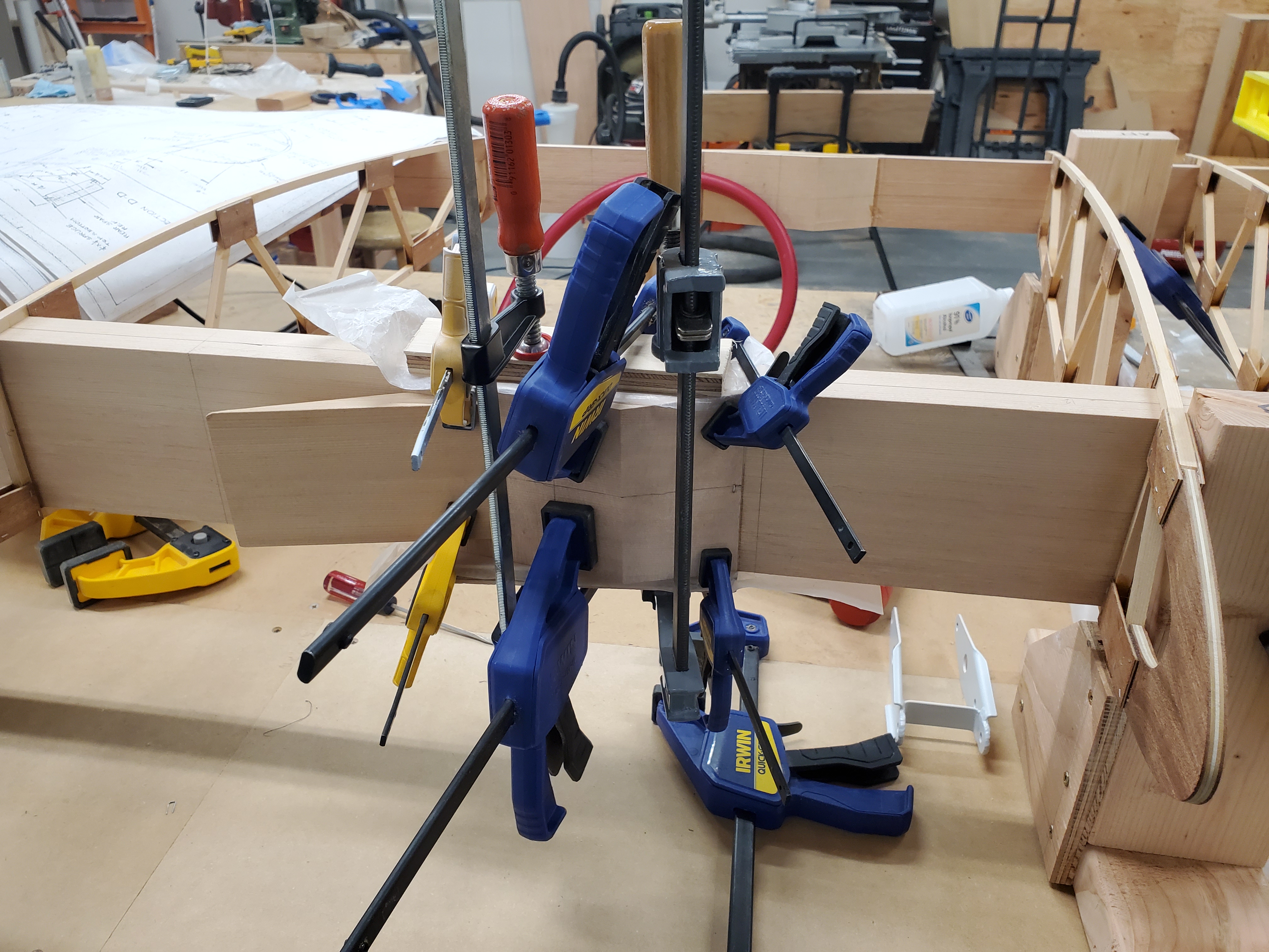
Many clamps. Many more will be needed later
Gluing the wedges in place takes a lot of clamps, and I used extra wedges to provide clamping surfaces, so the clamp didn't have to work on a slanted surface. As it was, I ended up stapling the ends of most of the wedges to keep them from squidging around on the lubricating coat of epoxy before it started to set up. Lots of wax paper strips kept the clamps from becoming a permanent part of the wing.
The little -238 wedges, which support the compression tubes where there's not also a steel bracket involved, proved to be more problematic that I'd hoped. At first, I was just stapling the thin edge, thinking that would be enough to keep it from wandering, but several of those wedges ended up twisted substantially off where they were supposed to be thanks to the epoxy-wander effect. I ended up re-drawing the centerlines on a number of wedges to ensure they'd be drilled in the right spot.
Drilling the Spar
Checking the alignment of the aileron pivots
The first holes to drill are those that sit at 90° to the spar: these can be done on the drill press, without ribs getting in the way. On the upper wing at least, it's really just the aileron pivot holes that can be done this way (the wing root fittings are the others, but those will wait until the two wings can be joined up, to ensure they're in the right place). In order to do this, I ran a straight piece of 1/4" steel rod through the three pivots, and made sure it could rotate freely before marking and drilling the mounting holes.
For the rest of them, how do you drill a straight, square hole in a 1.25" square wedge that sits at a 10° angle to the spar, with eleven loose ribs holding the other spar in their fragile grasp? Certainly not on the drill press, that's for sure. I ended up making two drilling jigs, the first of which was poorly considered. The one that worked was made from steel guide tubes clamped into quarter-inch thick aluminum rectangle extrusion, carefully milled to be square and straight. My attempts to weld the guide tube the first time were far too prone to warping, though others have had success with welding.
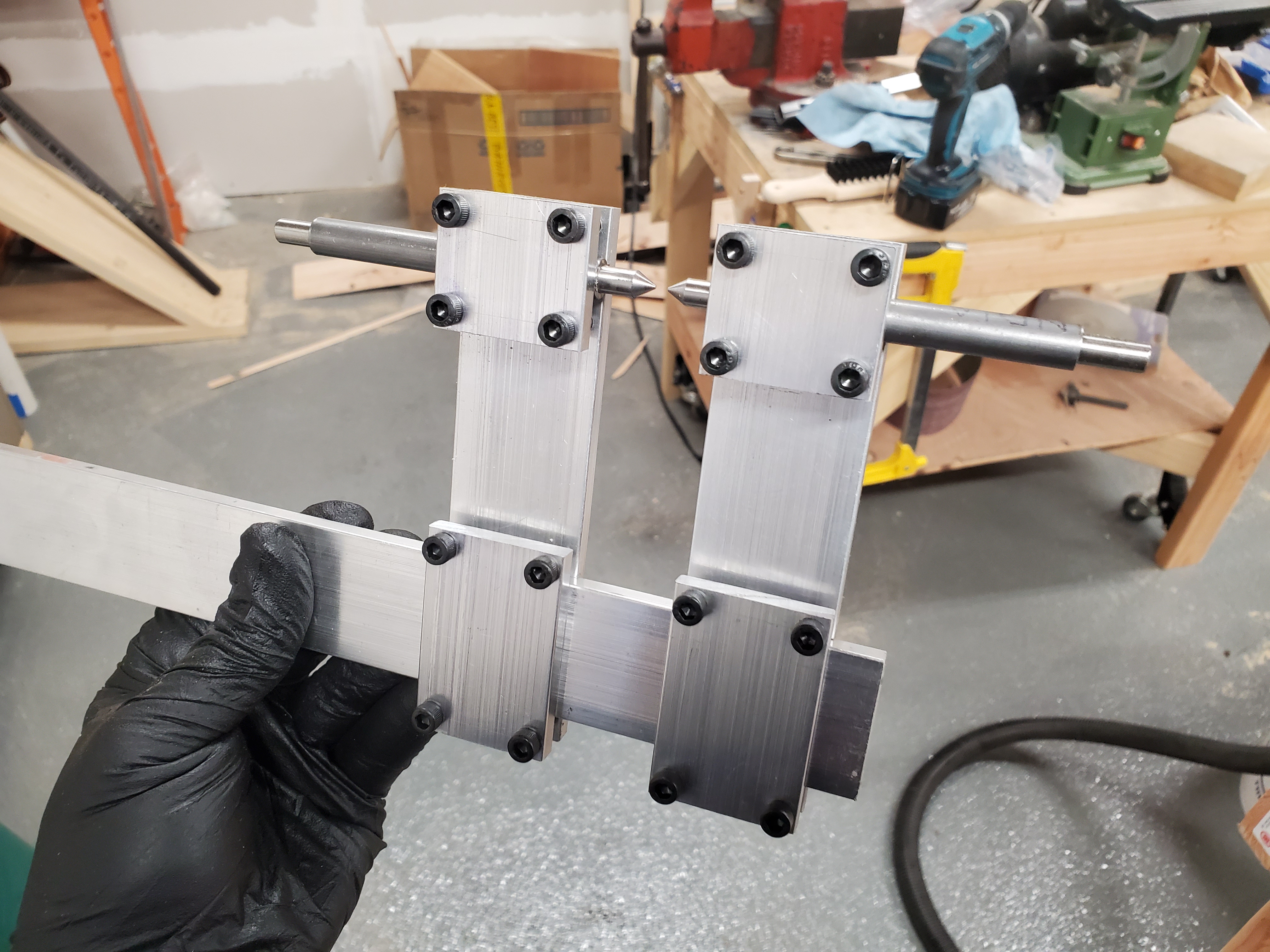
The drilling guide, Mk II. The pointed rods are for aligning
with a small hole in the material to be drilled
In addition to the drill guide tool, I turned points down on some 1/4" and 1/2" rods (the two sizes I would be using with the drill guide), and used them to physically index where the guide gets clamped: poke a hole where you want the hole centered in the spar, run the pointed guide into that hole, then use that physical connection to keep the guide aligned. The guide then gets clamped down so it won't move, and the actual drilling is kind of anti-climactic. I had to get a long 1/4" drill bit to fit through the guide tube, and still make any progress into the spar.
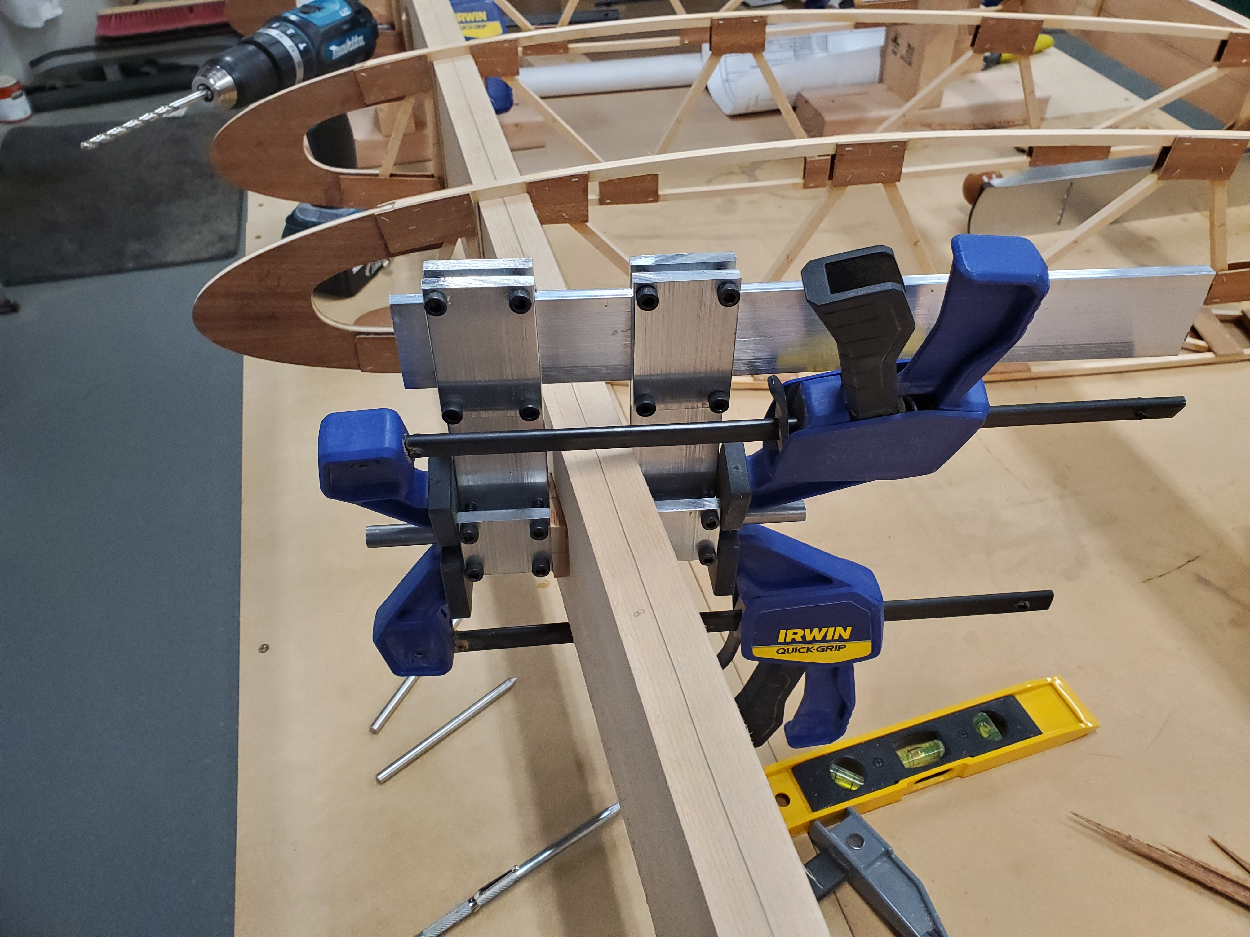
How the drill guide looks when it's in use
The 1/2" holes in the spar receive burly steel bushings, which take the 1/2" down to 5/16", and allow an AN5 bolt to pass nicely through. The bushing is there to deal with the tension of the flying and landing wires, which would otherwise bend bolts or pull through the wood of the spar.
And that brings me up to where I am right now. Two of four bushings made and installed into the wing, and four of five compression tubes temporarily fitted.

The current state of the wing
What's Next
Once I've finished fitting the bushings, I'll move on to fitting the drag wires. The plans call for drag strips, but I calculated that I could save a couple pounds of steel by using wires (the strips have to be oversize to deal with the weakening effect of welding, but the wires don't, so they can be smaller and lighter for the same strength).
Once the wires are installed, the compression tubes can be drilled and bolted for length, the wires tightened, and the wing "trammelled." Other builders have told me that keeping the spars straight and generally ensuring the 10° sweep angle is more important than trying to trammel individual drag wire sections -- due to the sweep angle, each of the drag wire sections is a different length, so the best you can do is set a trammel to calculated lengths based on trigonometric approximations, which is likely to be error-prone enough to offer only limited value. Better is to stretch a string (or possibly shine a laser) down the centerline of the spar, and ensure it stays straight that way.
After the wings are straight, the ribs are wedged and glued/nailed in place, and the next major parts tackled: the aileron can be built, all the plywood around the wing tank installed, the trailing edge installed, wingtip formed and installed, etc.
I'm using plywood leading edges rather than aluminum, and I've been advised that these shouldn't be installed until the wings can be installed and rigged on the fuselage, because it locks in the shape of the wing to such an extent.
It's exciting to finally be making something that looks like part of an airplane, rather than a weird little hunk of metal or wood. It's also exciting how fast it seems to be moving: from 2017 to the end of 2020, all I was doing was making weird little hunks of metal and wood, and although I was having a good time, it seemed like an endless task.
Now that I have all the weird little pieces made, the actual assembly of them into a complete wing is moving very quickly, and once I have this first wing built, subsequent wings will move even faster, since I have to work out the process on this one, but will have it pretty well down for the next wing. I just have to remember to mirror the plans in my brain, to make the next one a right wing instead of another left wing.
Posted at 23:49 permanent link category: /charger
Categories: all aviation Building a Biplane bicycle gadgets misc motorcycle theater